Troubleshooting Faulty Limit Switch Boxes
1. Failure Mode #1 – No Signal / Intermittent Signal
| Symptom | Possible Root Cause | Quick Check | Permanent Fix |
|---|---|---|---|
| No contact closure | Cam not actuating switch | Manually rotate shaft; listen for click | Re-adjust cam position |
| Intermittent open/close | Loose terminal wiring | Check screw torque | Use ferrules and thread-locking compound |
| Signal loss under vibration | Worn cam lobe | Measure cam profile with caliper | Replace with wear-resistant cam material |
| NO/NC logic reversed | Incorrect wiring configuration | Verify against wiring diagram | Re-terminate correctly |
Key takeaway: Over 40% of "dead" boxes are simply mis-adjusted cams or loose terminals—fixable in under 10 minutes.
2. Failure Mode #2 – Mechanical Switch Failure (Stuck / No Click)
| Symptom | Possible Root Cause | Quick Check | Permanent Fix |
|---|---|---|---|
| Switch does not click | Debris inside switch housing | Blow with clean, dry air | Use sealed switch type (IP67 minimum) |
| Click but no electrical change | Burned contacts | Measure contact resistance (should be <50 mΩ) | Replace switch element |
| Stuck in one position | Spring fatigue after high cycle count | Cycle test 50 times manually | Upgrade to higher-cycle-rated switch |
| Excessive actuation force | Cam profile too aggressive | Measure cam ramp angle | Use gradual-rise cam design |
Key takeaway: Mechanical switch life is directly tied to cycle count. Standard switches are rated for ~1M operations; heavy-duty versions offer 5M+ with sealed contacts.
3. Failure Mode #3 – Proximity / Inductive Sensor Failure
| Symptom | Possible Root Cause | Quick Check | Permanent Fix |
|---|---|---|---|
| No output when target present | Sensor gap too large | Check gap vs spec (typically 2–4 mm) | Re-gap or choose longer sensing range |
| False trigger | Ferrous metal debris on sensing face | Clean face with non-metallic brush | Use shielded sensor type |
| Output flickers | Voltage drop / supply instability | Measure supply at sensor terminals (should be within ±10%) | Add dedicated power supply or filter |
| Sensor dead after storm | Surge damage | Check for visible burn mark | Add surge suppressor or use protected sensor |
Key takeaway: Inductive sensors fail most often from wrong gap setting or transient voltage—not from the sensor itself. Proper installation prevents 80% of issues.
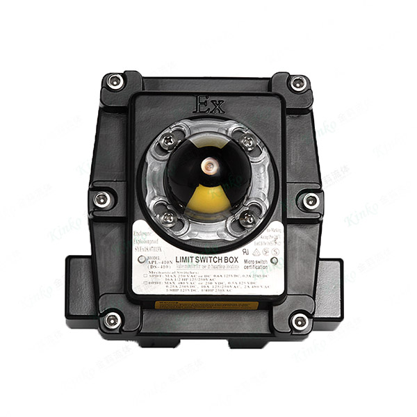
4. Failure Mode #4 – Water / Dust Ingress
| Symptom | Possible Root Cause | Quick Check | Permanent Fix |
|---|---|---|---|
| Corroded terminals | Failed O-ring/gasket | Inspect seal for cracks or flattening | Replace all seals annually |
| Condensation inside window | Temperature cycling + poor breather | Check breather vent (if equipped) | Use sealed box with desiccant breather |
| IP rating not maintained | Cable gland not tightened | Perform pull test on cable | Use double-compression glands |
| Dust accumulation on contacts | Insufficient enclosure rating | Check current IP rating vs environment | Upgrade to IP67 / NEMA 4X minimum |
Key takeaway: Ingress is the #1 killer of limit switch boxes in washdown, coastal, or dusty environments. A simple seal replacement kit costs a fraction of a new box.
5. Failure Mode #5 – Cam Wear / Slippage
| Symptom | Possible Root Cause | Quick Check | Permanent Fix |
|---|---|---|---|
| Switch triggers at wrong angle | Cam set screw loosened | Mark position; cycle 10 times; check drift | Use thread-locker and torque to spec |
| Gradual timing shift | Cam material wearing | Measure cam thickness vs new | Upgrade to glass-filled or metal cam |
| Uneven actuation | Shaft bearing wear causing wobble | Check radial play at shaft | Replace bearing with sealed ball type |
| No repeatability | Coupling backlash between valve stem and box shaft | Measure angular play | Upgrade to zero-backlash coupling |
Key takeaway: Cam wear is progressive—you lose positioning accuracy long before complete failure. Regular calibration checks (every 6 months) catch this early.
6. Failure Mode #6 – Electrical Noise / False Feedback
| Symptom | Possible Root Cause | Quick Check | Permanent Fix |
|---|---|---|---|
| False open signal | Inductive pickup from nearby motor cables | Run wires away from power cables (>300 mm) | Use shielded cable with grounded shield |
| Inconsistent voltage at PLC input | Long cable run with voltage drop | Measure voltage at PLC input | Use relay isolation or proximity with higher output |
| Chattering in noisy environment | No suppression diode across inductive load | Check for snubber circuit | Add RC snubber or varistor |
| Ground loop issues | Multiple ground points | Measure ground potential difference | Use single-point grounding |
Key takeaway: Electrical noise accounts for 25% of intermittent feedback issues—often misdiagnosed as mechanical failure. Always troubleshoot electrical environment before replacing hardware.
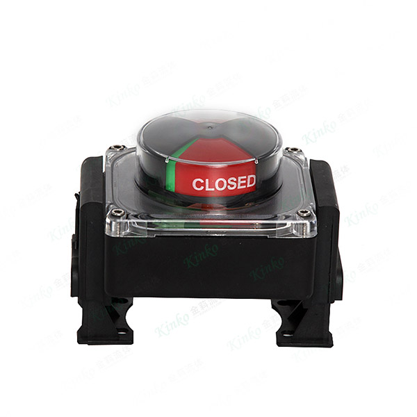
7. Quick Diagnostic Reference Table
| Symptom | Priority Check | Tools Needed | Typical Fix Time |
|---|---|---|---|
| No signal | Cam position + terminal torque | Hex key + screwdriver | 5 min |
| Intermittent signal | Vibration + wire continuity | Multimeter | 10 min |
| Stuck switch | Manual cycle test | None | 5 min |
| Ingress visible | Seal inspection | Visual | 15 min (seal replacement) |
| Timing drift | Angle measurement | Protractor / gauge | 10 min |
| Electrical noise | Cable routing + shielding check | Multimeter / oscilloscope | 30 min |
8. Procurement and Maintenance Checklist
To minimize limit switch box failures over the long term, specify and maintain with these criteria:
-
Enclosure rating: IP67 / NEMA 4X minimum for outdoor/washdown areas
-
Cam material: Reinforced polymer or metal—not basic nylon
-
Shaft bearing: Sealed ball type, not plain brass
-
Switch element: Gold-plated contacts for low-voltage applications
-
Cable entry: Dual-compression glands with strain relief
-
Calibration schedule: Re-check cam timing every 6 months
-
Spare seal kit: Stock on-site for quick replacement
9. Cost Impact of Ignoring Limit Switch Issues
| Issue | Consequence | Estimated Cost |
|---|---|---|
| False feedback → valve cycles unnecessarily | Packing wear + actuator fatigue | $500–$2,000/year |
| No feedback → process interlock trips | Unplanned shutdown | $5,000–$50,000 per event |
| Ingress → complete box replacement | Parts + labor + recalibration | $300–$800 per unit |
| Cumulative ignored wear → valve body damage | Forced rebuild | $2,500–$10,000 |
Ivan (Mobile:+86-18968769287)
WhatsApp:+86-13579991606
Wechat:+86-18968769287
Website:www.kinko-flow.com
ZHEJIANG KINKO FLUID EQUIPMENT CO.,LTD
