Best Practices for Maintaining Valve Accessories
1. Positioners: Calibration & Air Quality
The positioner is the most sensitive accessory in the loop. Its internal I/P converter and feedback electronics require clean, dry instrument air and periodic recalibration.
Best Practices:
-
Calibrate semi-annually: Even smart positioners with auto-calibrate features should be verified against a reference signal (e.g., 4–20 mA step test) to confirm linearity and hysteresis remain within tolerance.
-
Monitor air supply: Ensure the upstream FRL unit delivers air with a dew point at least 10°C below ambient temperature and particulate filtration of 5 microns or finer. Oil carryover is a leading cause of I/P converter blockage.
-
Check feedback linkage: Mechanical wear or loose coupling between the positioner feedback arm and the valve stem introduces position error. Inspect for play during routine rounds.
-
Review diagnostic data: If your positioner supports HART or Profibus, download stroke signatures and friction profiles to detect packing wear or seat degradation before they become critical.
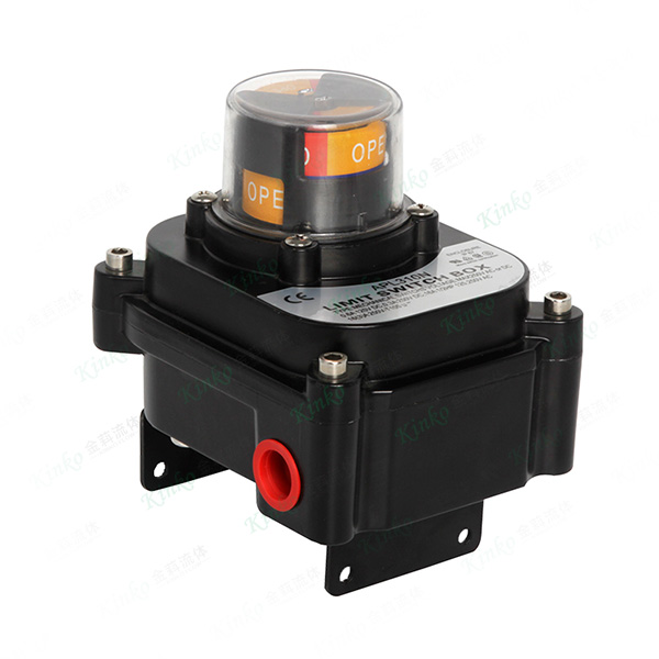
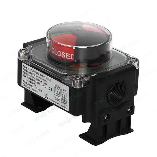
2. Limit Switches: Mechanical Wear & Contact Integrity
Limit switches are subjected to repeated mechanical actuation. Over time, cams wear, springs fatigue, and contacts oxidize.
Best Practices:
-
Inspect cams and levers: Check for burrs, deformation, or loosening of the cam set screws. Re-torque to specification.
-
Test contact continuity: Use a multimeter to verify that dry contacts close and open cleanly without intermittent resistance. Clean or replace contacts showing high resistance (above 50 milliohms).
-
Verify positive-opening action: For safety-rated switches, physically actuate the lever and confirm the contacts mechanically separate even when the electrical circuit is live.
-
Check seal integrity: Inspect housing gaskets and cable entries for moisture ingress. Replace desiccant breathers if installed.
-
Lubricate sparingly: Use only manufacturer-recommended lubricants on cam followers; excess grease attracts dust and accelerates wear.
3. Solenoid Valves: Coil Health & Pilot Ports
Solenoid valves convert electrical signals into pneumatic pressure. Their failure modes include coil burnout, armature sticking, and port clogging.
Best Practices:
-
Measure coil resistance: Periodically check coil resistance against the datasheet value. A deviation of more than 10% indicates imminent winding failure.
-
Verify rated voltage: Ensure supply voltage is within ±10% of the coil rating. Undervoltage causes sluggish actuation; overvoltage accelerates insulation breakdown.
-
Clean pilot ports: In dirty instrument air environments, the small pilot orifices can become obstructed. Remove and flush the valve body with clean solvent during overhauls.
-
Cycle test: For solenoids that remain de-energized for long periods (e.g., normally closed valves in standby), manually energize them monthly to prevent armature sticking.
4. FRL Units: Filter Elements & Lubricator Settings
The FRL is the first line of defense for the entire pneumatic loop. Neglect here accelerates wear on every downstream component.
Best Practices:
-
Replace filter elements: Change the 5-micron coalescing or particulate filter element every 6–12 months, or immediately if the pressure drop across the bowl exceeds 0.5 bar.
-
Drain bowls regularly: Automatic drains can fail. Manually check and drain water and condensate weekly, especially in humid climates.
-
Adjust lubricator feed: Set lubricator drip rate to 1–2 drops per minute per standard actuator. Over-lubrication causes sticky positioner spools; under-lubrication accelerates seal wear.
-
Inspect bowl integrity: Polycarbonate bowls can craze when exposed to solvents or UV. Replace if cracking or yellowing is visible.
5. General System-Wise Checks
Beyond individual components, consider these overarching practices:
| Activity | Frequency | Purpose |
|---|---|---|
| Leak test all fittings and tubing | Monthly | Prevent pressure loss and erratic actuator response |
| Verify fail-safe operation | Quarterly | Simulate loss of air or power; confirm valve moves to the safe position within the required time |
| Review torque output | Annually | Use a torque wrench to check actuator output at rated supply pressure; compare against original valve breakaway torque |
| Update maintenance logs | Per intervention | Track component replacements, calibration dates, and failure patterns for predictive planning |
The Cost of Neglect
A failed positioner costs more than the replacement part. It costs production stops, emergency call-out labor, and potentially unsafe process conditions. Conversely, a scheduled maintenance intervention during a planned outage costs a fraction of that.
By implementing the practices above, plants typically achieve:
-
30–50% reduction in unscheduled valve-related downtime
-
Extended service intervals for actuators and positioners by 2–3 years
-
Earlier detection of packing leakage and seat erosion
Ivan (Mobile:+86-18968769287)
WhatsApp:+86-13579991606
Wechat:+86-18968769287
Website:www.kinko-flow.com
ZHEJIANG KINKO FLUID EQUIPMENT CO.,LTD
