How Does a Motorized Ball Valve with Electric Actuator Enable Remote Operation?
1. The Short Answer: Full Remote Capability Through Digital Integration
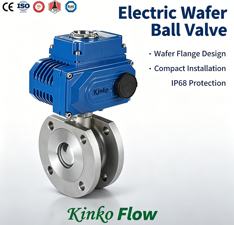
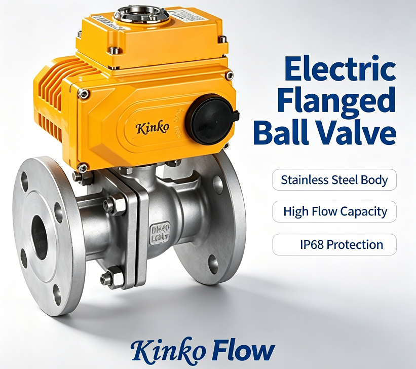
A motorized ball valve (ball valve + electric actuator) enables remote operation by converting an electrical control signal (4-20mA, dry contact, or digital bus) into mechanical rotation of the ball—without any manual intervention or pneumatic supply.
Remote operation capabilities:
-
Open/close from a DCS or PLC control room (hundreds of meters or kilometers away)
-
Modulating control for flow regulation (proportional positioning)
-
Status feedback (position, fault, cycle count) via hardwired or digital communication
-
Integration with SCADA, IoT platforms, and cloud-based asset management systems
This capability transforms a simple ball valve into a smart, network-connected final control element.
2. Core Technologies That Enable Remote Operation
Technology #1: Electric Actuator Drive System
The actuator contains a motor + gear train that converts electrical energy into mechanical torque. Key components:
-
Motor: AC induction (fixed speed) or brushless DC (variable speed)
-
Gearbox: Reduces motor RPM to produce high torque at low speed
-
Position feedback: Potentiometer, Hall-effect encoder, or absolute magnetic encoder
Remote capability: The motor starts/stops based solely on the received electrical signal—no operator presence required.
Technology #2: Control Signal Interface
| Signal Type | Operation | Remote Capability Level |
|---|---|---|
| Dry contact (OPEN/CLOSE) | Separate wires for open and close commands | Basic: On/Off from remote panel |
| 4-20mA analog | Modulating signal (e.g., 4mA=0%, 20mA=100%) | Advanced: Proportional positioning |
| 0-10V analog | Similar to 4-20mA, voltage-based | Advanced: Proportional positioning |
| Modbus RTU / Profibus / EtherNet/IP | Digital bus communication | Full: Control + diagnostics + parameterization |
| Wireless (LoRa, NB-IoT, Wi-Fi) | Radio signal transmission | Full: Control from anywhere with network coverage |
Technology #3: Position Feedback & Status Indication
Remote operation is not just about sending commands—it requires confirmation that the valve has responded correctly.
Feedback options:
| Feedback Type | Output Signal | Purpose |
|---|---|---|
| Mechanical visual dome | None (local visual only) | Operator confirmation when on-site |
| End-of-stroke limit switches | Dry contact (OPEN / CLOSED) | Remote status indication of full open/closed |
| 4-20mA position transmitter | Analog signal proportional to ball position | Modulating control confirmation |
| Digital bus feedback | Status, torque, temperature, cycle count, alarms | Full remote diagnostics |
| Bluetooth / NFC | Wireless local access | Smartphone configuration + troubleshooting via app |
Technology #4: Manual Override (Fail-Safe for Remote Operation)
When a valve is remotely operated, there must always be a local fallback in case of power/communication failure.
-
Handwheel: Manual gear drive for emergency operation (standard on most electric actuators).
-
Declutchable lever: For smaller actuators, a lever that disengages the motor gearbox.
-
Spring-return (fail-safe) actuator: Internal spring drives valve to a pre-defined safe position on power loss.
Remote operation benefit: Manual override ensures the valve can still be operated during emergencies, while the automation system remains in control during normal operation.
Technology #5: Communication Protocols for System Integration
To truly enable remote operation, the motorized ball valve must "speak" the language of the plant control system.
| Protocol | Physical Layer | Remote Capability |
|---|---|---|
| 4-20mA + HART | 2-wire analog + digital FSK overlay | Control + diagnostics + configuration |
| Modbus RTU | RS-485 (2-wire/4-wire) | Multi-drop; up to 247 devices per network |
| Modbus TCP/IP | Ethernet | Same as RTU, but TCP-based for wider area networks |
| Profibus PA | MBP (2-wire) | Process automation standard; intrinsic safety available |
| Profibus DP | RS-485 | Higher speed; factory automation |
| Foundation Fieldbus H1 | MBP (2-wire) | Advanced control in hostile environment |
| EtherNet/IP | Ethernet | Industrial Ethernet for Rockwell/Allen-Bradley integration |
| LoRaWAN / NB-IoT | Wireless (unlicensed/licensed bands) | Remote sites, pipeline monitoring, water distribution |
Technology #6: Smart Diagnostics for Remote Troubleshooting
Remote operation is only valuable if you can also diagnose problems remotely.
Diagnostic parameters available on modern electric actuators:
-
Stall detection: Actuator stops due to obstruction (torque/current exceeds limit)
-
Cycle count: Tracks total strokes for preventive maintenance scheduling
-
Run time: Motor running time per cycle (increases when packing friction rises)
-
Temperature: Internal actuator temperature (overheat alarm)
-
Power interruption log: Records last power loss event and valve position at that time
-
Partial stroke test (PST): For SIL-rated safety loops—can be initiated remotely
Benefit: Maintenance teams can diagnose 70% of issues without visiting the valve—reducing field service calls and increasing plant availability.
3. Performance Comparison: Motorized Ball Valve vs. Pneumatic Ball Valve for Remote Operation
| Feature | Motorized Ball Valve | Pneumatic Ball Valve |
|---|---|---|
| Remote control signal | 4-20mA / Digital bus / Dry contact | 4-20mA (I/P) or solenoid (3/2, 5/2) |
| Power requirement | 24V DC / 110V AC / 230V AC | Instrument air + (optional) electrical for solenoid |
| Communication integration | Native digital bus (Modbus, Profibus, etc.) | Requires smart positioner for bus communication |
| Position feedback | Built-in (encoder/limits) | Requires separate limit switch box + position transmitter |
| Diagnostic data | Extensive (motor torque, temp, cycle count, etc.) | Limited unless using smart positioner with diagnostics |
| Fail-safe on power loss | Spring-return (optional) or battery/UPS | Spring-return or volume tank (external) |
| Manual override | Handwheel (standard) | Handwheel (optional, requires extra cost) |
| Remotely adjustable parameters | Yes (deadband, stroke time, torque limits) | Limited (requires positioner adjustment) |
| Ideal for long-distance (>100m) | Excellent (no pressure drop in signal lines) | Acceptable (air lines >100m have lag) |
| Ideal for network integration | Excellent (native protocol support) | Good (requires positioner + gateway) |
| Relative cost (valve + actuator) | Medium | Low (if air available) |
4. Technical Specification Table – Typical Motorized Ball Valve for Remote Operation
| Parameter | Typical Range / Options |
|---|---|
| Valve size | DN15 ~ DN300 (1/2" ~ 12") |
| Valve design | Floating ball (≤DN80) / Trunnion-mounted (≥DN100) |
| Body material | WCB, CF8M (316SS), CF3M (316L), Duplex, Inconel |
| Seat material | PTFE, RPTFE, PEEK, PPL, Metal |
| Pressure rating | PN16 ~ PN420 / ANSI 150 ~ 2500 |
| Actuator type | Quarter-turn electric actuator |
| Supply voltage | 24V DC, 110V AC, 230V AC (50/60 Hz) |
| Control signal | 4-20mA, 0-10V, Dry contact, Modbus, Profibus, EtherNet/IP |
| Position feedback | 4-20mA (analog) + dry contact (limits) + digital bus |
| Positioning accuracy | ±0.5% ~ ±1.0% full stroke |
| Stroking time (90°) | 3~30 seconds (depending on torque and gear ratio) |
| Enclosure rating | IP67 / IP68 / NEMA 4X / NEMA 6P |
| Ex certification | ATEX / IECEx / CSA (Zone 1, Zone 2, Class I Div 1/2) |
| Manual override | Handwheel (standard) or declutchable lever |
| Operating temperature | -40°C ~ +85°C (standard) / -60°C ~ +200°C (special) |
| Communication protocols | HART, Modbus RTU, Modbus TCP, Profibus PA/DP, Foundation Fieldbus, EtherNet/IP |
| Diagnostic capability | Motor current monitoring, cycle count, run time, stall detection, temperature logging |
5. Remote Operation Scenarios – Typical Applications
| Scenario | Why Motorized Ball Valve Wins | Communication Used |
|---|---|---|
| Pipeline block valve (gas/oil) | Operate from central control room; no instrument air lines over long distances | Modbus RTU (RS-485) or satellite |
| Water treatment plant (remote wells) | No air infrastructure at well sites; solar-powered 24V DC operation | 4-20mA + LoRaWAN |
| Chemical reactor feed control | Precise modulating control with digital diagnostics for batch consistency | Profibus PA / Foundation Fieldbus |
| HVAC chilled water system | Controlled from building BMS; quiet operation; no air exhaust noise | BACnet over Modbus or EtherNet/IP |
| Tank farm emergency shut-off | Fail-safe spring-return + remote ESD trigger via DCS | Hardwired dry contact (ESD) + Modbus for status |
| Offshore platform (no air) | All-electric saves space; eliminates offshore air compressor maintenance | Modbus TCP over fiber optic |
| Remote mining site (desert) | Solar-powered 24V DC; radio communication to central monitoring station | Wireless (LoRa or cellular) |
Ivan (Mobile:+86-18968769287)
WhatsApp:+86-13579991606
Wechat:+86-18968769287
Website: www.kinko-flow.com
ZHEJIANG KINKO FLUID EQUIPMENT CO.,LTD
