Need a Reliable Electric Actuator for Your Ball Valve?
How Electric Actuators Work with Ball Valves
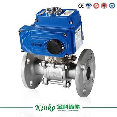
A ball valve uses a spherical disc (the ball) with a bore through its center. Rotating the ball 90° aligns the bore with the pipe (open) or blocks it (closed). The electric actuator replaces the manual handwheel or lever with a motorized drive that rotates the valve stem electrically.
The actuator receives an electrical signal—either a simple open/close command or a continuous analog signal for modulating control—and drives the motor to position the valve accordingly. Many electric actuators also include feedback mechanisms to confirm the valve's actual position.
Key advantages of electric actuation for ball valves:
-
No reliance on plant air supply
-
Precise positioning for throttling applications
-
Easy integration with PLC and DCS systems
-
Lower ongoing energy costs in many applications
-
Clean operation (no air exhaust)
Step 1: Determine Your Ball Valve's Torque Requirement
The most critical factor in electric actuator selection is torque. The actuator must deliver enough rotational force to operate the valve reliably under all process conditions.
Ball valves have two distinct torque values to consider:
Breakaway torque – The force required to start the ball moving from a closed position. This is the highest torque point due to seat compression and static friction. It increases with higher differential pressure and temperature.
Running torque – The force required to keep the ball rotating after it has started moving. This is significantly lower than breakaway torque.
Selection rule: Choose an actuator with a rated torque that exceeds the valve's maximum breakaway torque by a safety margin of at least 20-30%. This margin accommodates pressure fluctuations, temperature changes, and wear over the valve's service life.
| Torque Factor | Description | Impact on Actuator Selection |
|---|---|---|
| Breakaway Torque | Highest force needed (starting from closed) | Determines minimum actuator torque rating |
| Running Torque | Lower force needed during rotation | Less critical but affects cycle life |
| Seating Torque | Force needed for tight shut-off | May require extra torque at end of stroke |
| Differential Pressure | Pressure across the ball at opening | Directly increases breakaway torque |
| Temperature | Thermal expansion of seats and ball | Increases friction and torque requirements |
Step 2: Match the Actuator Duty Cycle to Your Application
Electric actuators are rated by duty cycle—the percentage of time they can operate without overheating.
Standard duty (S2/S4): Suitable for intermittent operation, such as infrequent valve adjustments or daily open/close cycles.
Continuous duty (S1): Designed for applications requiring constant operation, such as modulating control where the actuator is continuously adjusting position.
High-cycle duty: For applications with frequent operation (e.g., packaging lines or batching processes), choose actuators with enhanced motor and gear train designs.
Consideration: The duty cycle rating directly affects the actuator's service life. Undersizing duty cycle leads to premature motor burnout and unplanned downtime.
Step 3: Power Supply and Control Signal Selection
Electric actuators are available with various power supply and control options. Ensure compatibility with your existing electrical infrastructure.
Power supply options:
-
AC voltage (typically 110V, 220V, 380V)
-
DC voltage (typically 12V, 24V)
-
Solar-compatible (for remote applications)
Control signal options:
-
On/off (open or close) – for basic two-position control
-
4-20mA analog – for modulating (throttling) control
-
0-10V analog – alternative modulating signal
-
Bus communication (e.g., Modbus, Profibus) – for networked systems
Feedback options:
-
Limit switches (dry contacts) – for position confirmation
-
Potentiometer – for analog position feedback
-
Encoder – for high-precision position reporting
Step 4: Speed and Stroke Time
Different applications require different operating speeds.
Fast stroking: For emergency shutdown or rapid cycling applications. Faster speeds reduce process response time but increase motor current draw.
Slow stroking: For applications requiring gentle valve operation to prevent water hammer or pressure surges. Slow operation extends valve seat life.
Selection tip: Most ball valves operate best with a stroke time between 5 and 30 seconds, depending on line size and media. Larger valves typically require slower speeds due to greater inertia and torque requirements.
Step 5: Environmental and Safety Considerations
The installation environment significantly impacts actuator material selection and enclosure requirements.
Temperature extremes: Standard electric actuators typically operate between -10°C and +60°C. For ambient temperatures outside this range, special lubricants, motor insulation, or heating/cooling elements may be required.
Moisture and dust: Enclosure ratings define protection levels. For outdoor or washdown areas, higher-rated enclosures provide protection against water ingress. For dusty environments, dust-tight enclosures are recommended.
Corrosive atmospheres: Chemical plants, coastal installations, and marine environments require actuators with corrosion-resistant housings (stainless steel or specialized coatings).
Hazardous areas: For locations with explosive atmospheres, select actuators with appropriate international certifications. These actuators are designed to prevent ignition under fault conditions.
Ivan (Mobile:+86-18968769287)
WhatsApp:+86-13579991606
Wechat:+86-18968769287
Website: www.kinko-flow.com
ZHEJIANG KINKO FLUID EQUIPMENT CO.,LTD
